
Knight Board Specs
Knight Board
Section titled “Knight Board”The Knight Board is NeuroPawn’s core biopotential acquisition PCB. It is designed for 8-channel EEG, EMG, ECG, EOG, and general ExG acquisition over a USB-C connection.
EEG Sensors
Section titled “EEG Sensors”| Parameter | Value |
|---|---|
| Channels | 8, adjustable gain (1 – 12) |
| Reference | Auricular (ear clip) |
| Electrode types | Dry spike, wet spike, gold-cup, EMG, ECG, active |
EEG Signals
Section titled “EEG Signals”| Parameter | Value |
|---|---|
| Sampling method | Referential or bipolar montage, 8 × 16-bit ADC |
| Supported sample rates | 125 / 250 / 500 SPS |
| Default sample rate | 125 SPS |
| Detection range | ±4.19 mV to ±50.3 mV differential, gain dependent |
| Detection step | 0.128 – 1.53 µV/count, gain dependent |
| Bandwidth | 1 – 62.5 Hz |
| Filtering | Common-mode noise filter, 50/60 Hz notch (2nd order) |
| CMRR | 120 dB |
| Software | BrainFlow, LSL, NeuroPawn EXG Visualizer |
Connectivity & Power
Section titled “Connectivity & Power”| Parameter | Value |
|---|---|
| Connection | USB-C (bus-powered) |
| Operating voltage | 5 V |
| Streaming | Real-time |
Channel Switches
Section titled “Channel Switches”Each of the 8 input channels has a dedicated slide switch on the board.
- Switch toward the header — channel OFF (common reference input disconnected)
- Switch away from the header — channel ON (common reference input active)
Channels are labelled 1 – 8 on the silkscreen. Unused channels should be switched off to minimise crosstalk and noise on adjacent active channels. For simplicity, we say that switches “turn off” channels, in reality this is not what is happening. Switching toward the headers routes the channel’s negative input directly to the header instead of the common reference pin. In some instances, users may want to have individually addressable references for experiments that involve capturing 2 different types of biosignals (example: EEG, and EoG).
Electrode Connector Pinout
Section titled “Electrode Connector Pinout”Each channel exposes a negative (N) and a positive (P) input. Channels are
labelled on the board in the form N X P, where:
- N is the negative input on the left rail,
- X is the channel number (1 – 8),
- P is the positive input on the right rail.
For example, channel 3’s inputs are labelled N3 (left) and 3P (right).
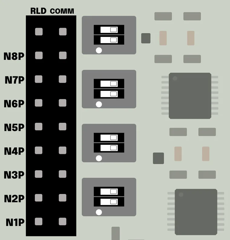
| Pin label | Description |
|---|---|
N1 – N8 | Negative input for channels 1–8 (left rail) |
1P – 8P | Positive input for channels 1–8 (right rail) |
COMM | Common reference input (connect to reference electrode, e.g. ear clip) |
RLD | Right-leg drive output (connect to driven reference electrode for noise reduction) |
Gain Settings
Section titled “Gain Settings”The Knight Board supports per-channel programmable gain. The default gain is 12. Available values are 1, 2, 3, 4, 6, 8, 12.
The voltage scale factor — the number of microvolts represented by each raw count — is derived from the ADC’s full-scale reference, its 16-bit signed resolution, the fixed analog front-end gain of 79.57, and the selected ADC gain:
At the default gain of 12, this works out to an ADC step voltage of ≈ 0.128 µV/count.
| Gain | Scale factor | Input range |
|---|---|---|
| 1 | 1.534 µV/count | ±50.3 mV |
| 2 | 0.767 µV/count | ±25.1 mV |
| 3 | 0.511 µV/count | ±16.8 mV |
| 4 | 0.384 µV/count | ±12.6 mV |
| 6 | 0.256 µV/count | ±8.38 mV |
| 8 | 0.192 µV/count | ±6.28 mV |
| 12 (default) | 0.128 µV/count | ±4.19 mV |
In firmware/driver code the same calculation appears as:
float eeg_scale = 4 / float ((pow (2, 15) - 1)) / 79.57 / 12 * 1000000.;To select a gain in BrainFlow, pass it through other_info:
params.other_info = '{"gain": 6}' # any value from: 1, 2, 3, 4, 6, 8, 12